
5. Sustainable Cities and Communities
Sustainable Cities and Communities is the 11th Sustainable Development Goal which aspires to make cities inclusive, safe, resilient and sustainable.The world is becoming increasingly urbanized. Since 2007, more than half the world’s population has been living in cities. This makes it very important for the cities to remain alert when there is a chance of disaster like floods. Local administration should know if their city is going to get affected by the rains which happen in their proximity so that they can raise an alert amongst the citizens. This exercise will solve one of such problems.

5.1. Problem: City getting affected by rain or not
Problem Statement
To determine the areas where if it rains will affect a city/town
Core Idea
If it rains in vicinity of a river connecting the city, the city will get affected by the rains.
Approach
Choose a city
Get the Rivers (Edges)
Create river components
Create a Buffer around the city
Finding the components intersecting the buffer
Finding the rain zones
5.2. Choose a city
For this exercise, Munshigang city from Bangladesh is chosen. This city has multiple rivers in its proximity which makes it an apt location to demonstrate this exercise. The exercise will try to find the areas, where if it rains the city will be affected. To define the location of this city and use it in for further steps, create a table to store the name along with latitude and longitude values of City’s location. This stores the city as a point.
5.2.1. Exercise 1: Create a point for the city
1CREATE TABLE city_vertex (id BIGINT, name TEXT, geom geometry);
2INSERT INTO city_vertex(id, name, geom) VALUES (
35,'Munshigang', ST_SetSRID(ST_Point(89.1967,22.2675),4326));
Latitude and longitude values are converted into geometry form using ST_Point
which returns a point with the given X and Y coordinate values. ST_SetSRID is used
to set the SRID (Spatial Reference Identifier) on the point geometry to 4326.
5.3. Pre-processing waterways data
First step is to pre-process the data obtained from Data for Sustainable Development Goals. This section will work the graph that is going to be used for processing. While building the graph, the data has to be inspected to determine if there is any invalid data. This is a very important step to make sure that the data is of required quality. pgRouting can also be used to do some Data Adjustments. This will be discussed in further sections.
5.3.1. Setting the Search Path of Waterways
First step in pre processing is to set the search path for Waterways
data. Search path is a list of schemas that helps the system determine how a
particular table is to be imported.
5.3.1.1. Exercise 2: Inspecting the schemas
Inspect the schemas by displaying all the present schemas using the following command
\dn
   List of schemas
   Name    |  Owner
-----------+----------
 public    | postgres
 waterway  | <user-name>
(2 rows)
The schema names are waterway and public. The owner depends on who has the rights to the database.
5.3.1.2. Exercise 3: Inspecting the search path
Display the current search path using the following query.
SHOW search_path;
   search_path
-----------------
 "$user", public
(1 row)
This is the current search path. Tables cannot be accessed using this.
5.3.1.3. Exercise 4: Fixing the search path
In this case, search path of roads table is set to waterways schema. Following query
is used to fix the search path
SET search_path TO waterways,public;
SHOW search_path;
    search_path
-------------------
 waterways, public
(1 row)
5.3.1.4. Exercise 5: Enumerating tables
Finally, \dt is used to verify if the Schema have bees changed correctly.
\dt
                     List of relations
  Schema   |            Name             | Type  |  Owner
-----------+-----------------------------+-------+---------
 public    | spatial_ref_sys             | table | <user-name>
 waterways | configuration               | table | user
 waterways | waterways_pointsofinterest  | table | user
 waterways | waterways_ways              | table | user
 waterways | waterways_ways_vertices_pgr | table | user
(5 rows)
5.3.1.5. Exercise 6: Counting the number of Waterways
The importance of counting the information on this workshop is to make sure that the same data is used and consequently the results are same. Also, some of the rows can be seen to understand the structure of the table and how the data is stored in it.
1SELECT count(*) FROM waterways_ways;
5.3.2. Exercise 7: Removing the Rivers which are in swamps
This exercise focusses only the areas in the mainland, where if it rains the city is
affected. Hence, the rivers which are there in the swamp area have to be removed
from the waterways_ways table.
1DELETE FROM waterways_ways
2WHERE osm_id
3IN (721133202, 908102930, 749173392, 652172284, 126774195, 720395312);
5.4. pgr_connectedComponents for preprocessing waterways
For the next step pgr_connectedComponents will be used. It is used to find the
connected components of an undirected graph using a Depth First Search-based approach.
Signatures
pgr_connectedComponents(edges_sql)

RETURNS SET OF (seq, component, node)
OR EMPTY SET
pgr_connectedComponents Documentation can be found at this link for more information.
5.5. Exercise 8: Get the Connected Components of Waterways
As the rivers in the data are not having single edge, i.e, multiple edges make up
a river, it is important to find out the connected edges and store the information
in the waterways_ways table. This will help us to identify which edges belong to
a river. First, the connected components are found and then stored in a new column
named component.
pgRouting function pgr_connectedComponents is used to complete this task.
A sub-query is created to find out all the connected components. After that,
the component column is updated using the results obtained from the sub-query.
This helps in storing the component id in the waterways_ways_vertices_pgr table.
Next query uses this output and stores the component id in the waterways_ways
(edges) table. Follow the steps given below to complete this task.
Add a column named
componentto store component number.
1ALTER TABLE waterways_ways_vertices_pgr
2ADD COLUMN component INTEGER;
3
4ALTER TABLE waterways_ways
5ADD COLUMN component INTEGER;
Get the Connected Components of Waterways
 1UPDATE waterways_ways_vertices_pgr SET component = subquery.component
 2FROM (SELECT * FROM pgr_connectedComponents(
 3'SELECT gid AS id, source, target, cost, reverse_cost FROM waterways_ways')
 4) AS subquery
 5WHERE id = node;
 6
 7UPDATE waterways_ways SET component=a.component FROM (
 8SELECT id, component FROM waterways_ways_vertices_pgr
 9) AS a
10WHERE id = source;
With component id stored in both vertex and edge table of waterways, lets proceed to next step.
5.6. Exercise 9: Creating buffer around the city
Create a buffer around the city to define an area, inside which the intersection
of rivers would be found. ST_Buffer is used to create this buffer. Follow the
steps given below to complete this task.
Adding column to store Buffer geometry
1ALTER TABLE waterways.city_vertex
2ADD COLUMN city_buffer geometry;
Storing Buffer geometry
1UPDATE waterways.city_vertex
2SET city_buffer = ST_Buffer((geom),0.005)
3WHERE  name = 'Munshigang';
Displaying the results of Buffer operation
1SELECT city_buffer FROM waterways.city_vertex;
5.6.1. Exercise 10: Creating a function that gets the city buffer
A function can be created for the same task. This will be help when the table has more than one city.
1CREATE OR REPLACE FUNCTION get_city_buffer(city_id INTEGER)
2RETURNS geometry AS
3$BODY$
4SELECT city_buffer FROM city_vertex WHERE id = city_id;
5$BODY$
6LANGUAGE SQL;
5.7. Exercise 11: Finding the components intersecting the buffer
Next step is to find the components of waterways which lie in the buffer zone of
the city. These are the waterways which will affect the city when it rains around
them. This is done using ST_Intersects. Note that get_city_buffer function
is used in the query below.
1SELECT DISTINCT component
2FROM waterways.city_vertex, waterways.waterways_ways
3WHERE ST_Intersects(the_geom, get_city_buffer(5));
Output shows the distinct component numbers which lie in the buffer zone of the city. Next step is to get all the edges that have those components.
5.8. Exercise 12: Get the rain zones
This is the final step of the exercise. In this, the area where if it rains, the
city would be affected, also can be called as rain zone is being found. For this,
create a Buffer around the river components. First, add columns named rain_zone
in waterways_ways to store buffer geometry of the rain zones. Then, find the buffer
for every edge which intersects the buffer area using ST_Buffer and update the
rain_zone column. Follow the steps given below to complete this task.
Adding column to store Buffer geometry
1ALTER TABLE waterways_ways
2ADD COLUMN rain_zone geometry;
Storing Buffer geometry
1UPDATE waterways.waterways_ways
2SET rain_zone = ST_Buffer((the_geom),0.005)
3WHERE ST_Intersects(the_geom, get_city_buffer(5));
This will give us the requires area, where if it rains, the city will be affected.
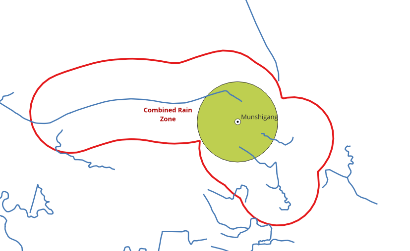
5.9. Exercise 13: Create a union of rain zones
Multiple polygons that are obtained can also be merged using ST_Union. This
will give a single polygon as the output.
1SELECT ST_Union(rain_zone) AS Combined_Rain_Zone
2FROM waterways_ways;